Assembly · Step 2 of 4
Assembling the Frame
This is Step 2 of 4 of Green Divider assembly, focusing on the metal frame construction. Ensure the wooden boxes from Step 1 are fully assembled before beginning.
Watching the video assembly guide before starting is highly recommended.
Assembly Video
Opens at the metal frame section. Watching the full video before beginning is highly recommended.
Build the frame where the Green Divider will stand. Once the tank is filled and the boxes are planted, it is much harder to move.
Reference
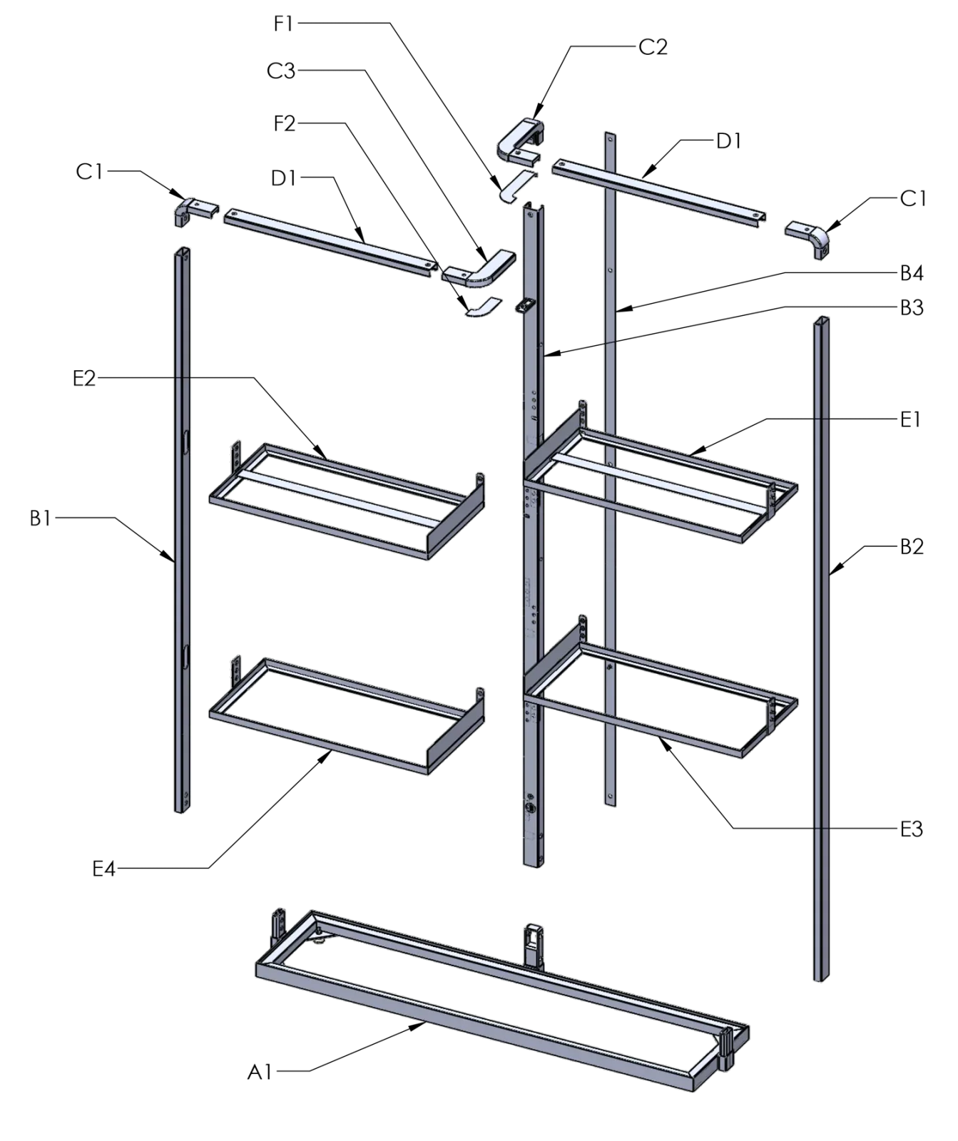
Frame parts & hardware
Every part carries a label sticker (A1, B1, E1…). Leave the stickers on until the frame is built; you remove them at the end of this step.
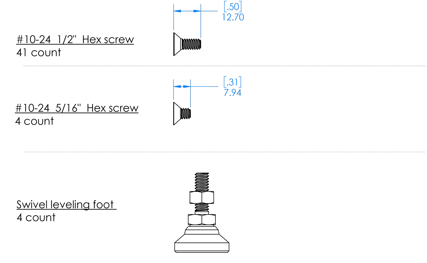
The kit also holds four #10-24 × 5⁄16″ hex screws, used only for the top brackets in Steps 4–5, and four swivel leveling feet.
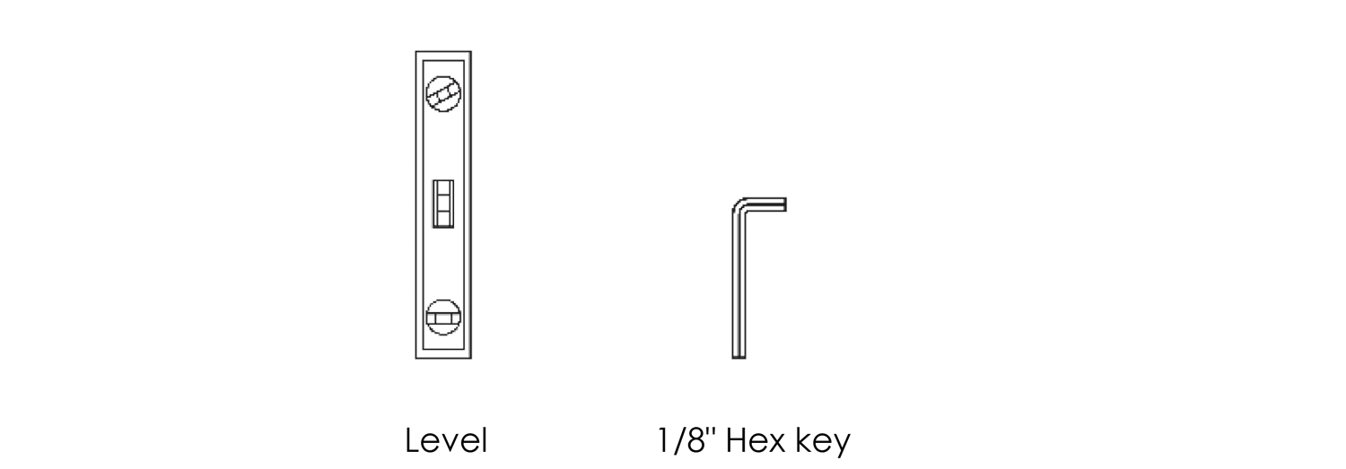
Tools Required
Assembly Steps
Leveling feet
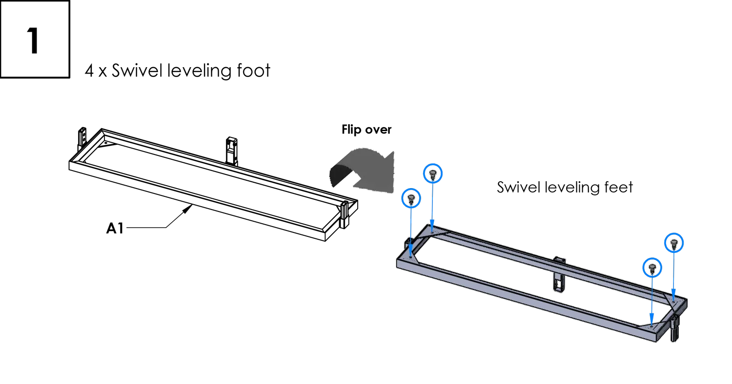
Flip the Base Frame (A1) upside down and screw the four swivel leveling feet into its corners.
Flip the frame back over. Thread a hex nut down each foot and tighten it against the frame.
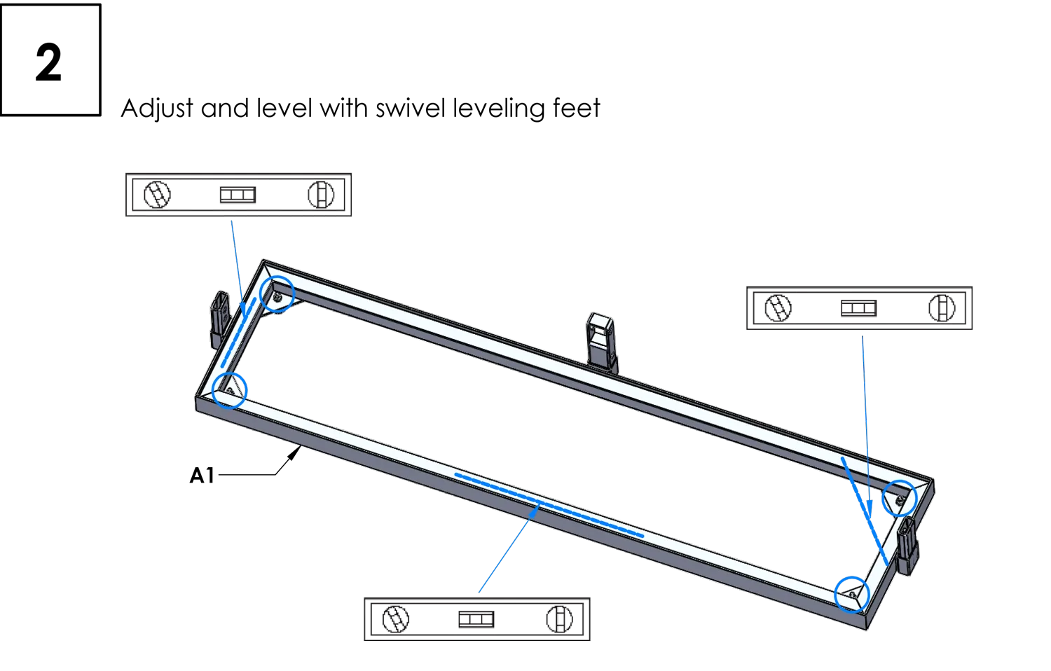
Level the base
Set a level along the front, along the back, and across both ends.
Adjust the feet until A1 is level in every direction.
Stand the support bars
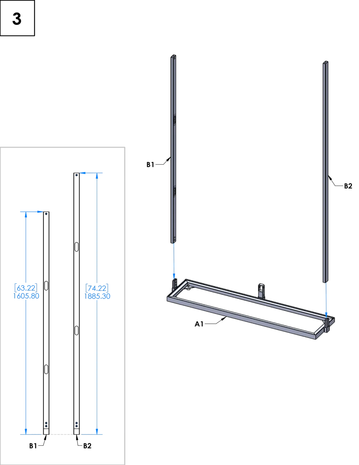
Seat the Left Side Support Bar (B1), the shorter one at 63¼″, in the left socket of A1.
Seat the Right Side Support Bar (B2), the taller one at 74¼″, in the right socket.
Seat the Back Support Bar (B3) in the center socket.
Build the top brackets
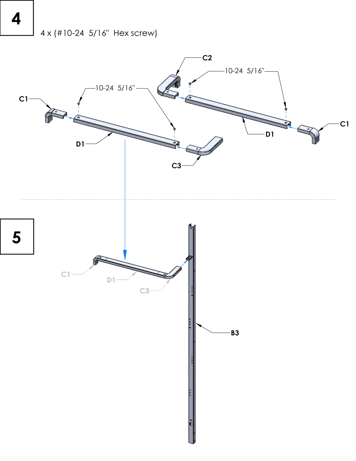
Use the 1/8″ hex key and the four #10-24 × 5⁄16″ screws, one per joint.
Left Top Bracket: join D1 to C3, then C1 to the other end of D1.
Right Top Bracket: join D1 to C2, then C1 to the other end.
Lift the Left Top Bracket and hook C3 into the slot near the top of B3.
Seat the Left Top Bracket
With C3 hooked into B3, lower C1 onto the top of B1. B3 sits in the center socket of A1.
Don’t add screws yet. Everything is fastened in Step 8.
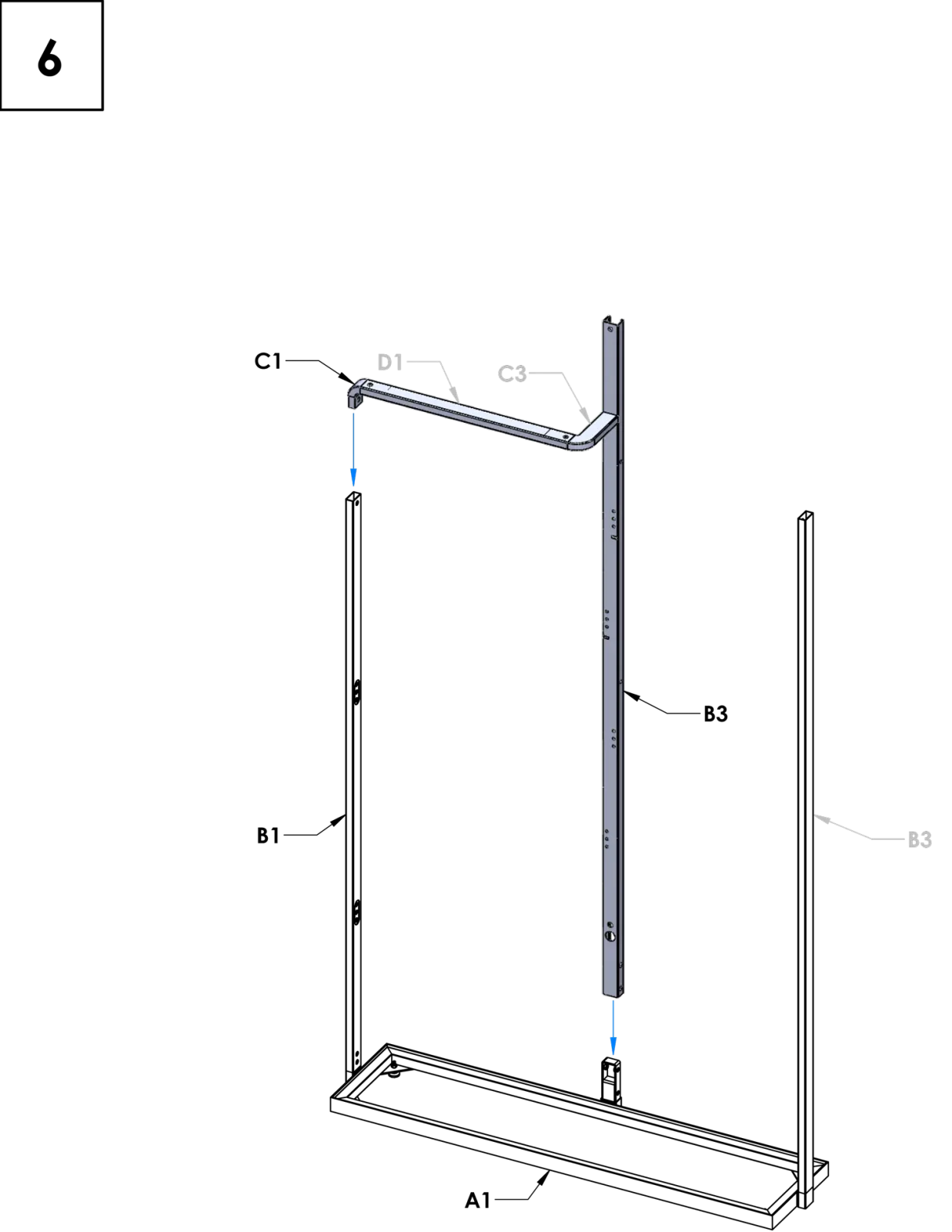
Seat the Right Top Bracket
Lift the Right Top Bracket into place. Seat C2 on top of B3, and C1 on top of B2.
The taller right side should now be closed at the top.
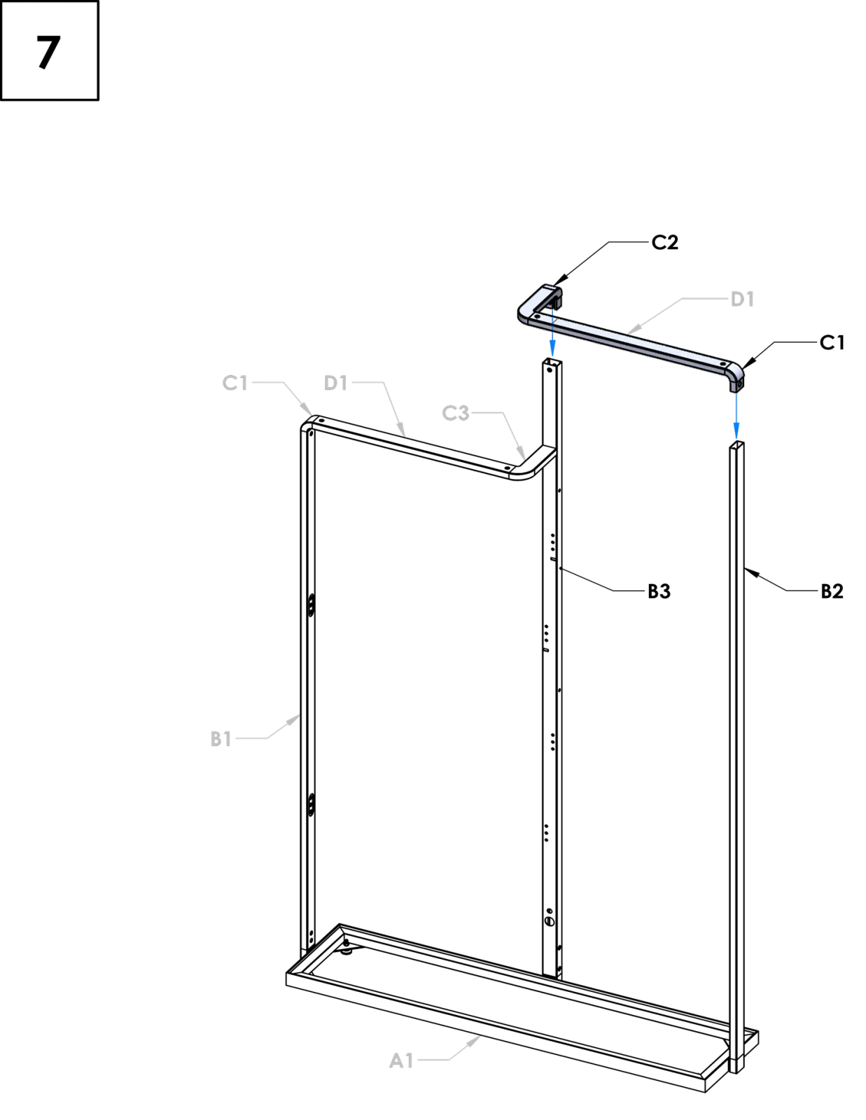
Fasten the brackets and support bars
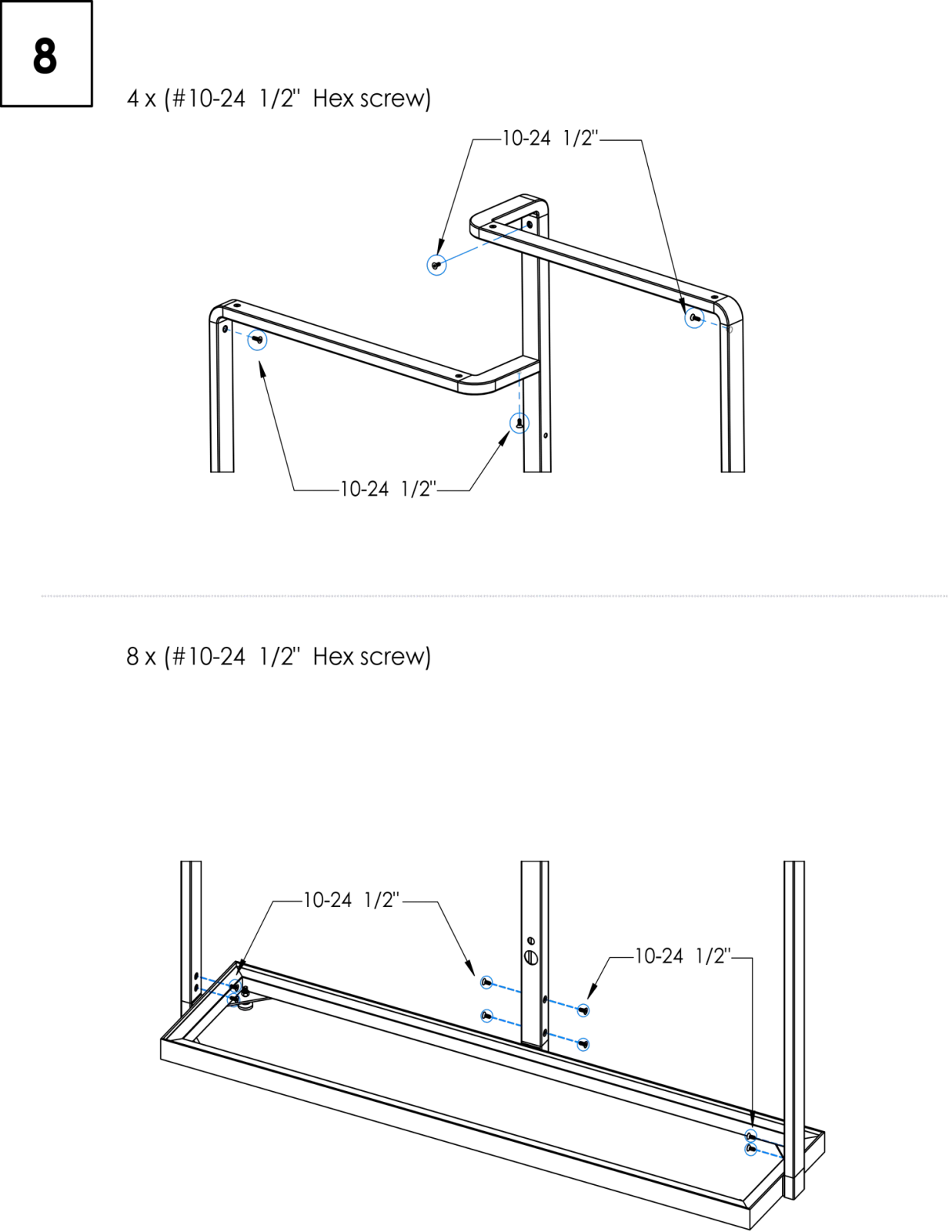
Top: drive four #10-24 × ½″ screws through the top brackets into the support bars, one at each connection circled in the diagram.
Base: drive eight #10-24 × ½″ screws where B1, B2 and B3 meet A1: two at B1, four at B3 (two per side), and two at B2.
Install box frames E1, E2 and E3
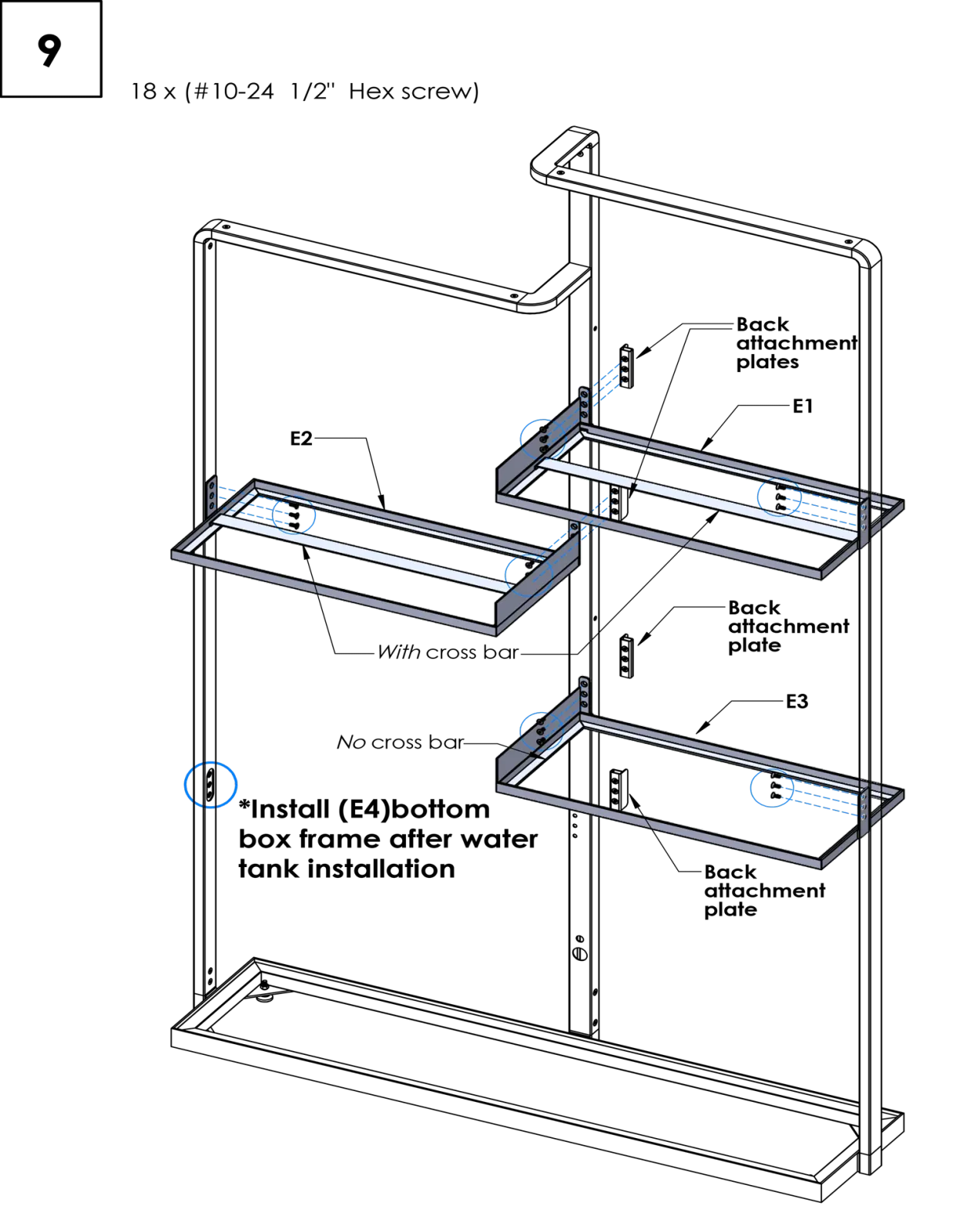
Frames with a cross bar go on top: E1 top right, E2 top left. E3, with no cross bar, goes bottom right.
Loosely start three ½″ screws into the side support bar. Don’t tighten yet.
At B3, line up the frame’s bracket and a Back Attachment Plate with the three holes.
Pinch the bracket and frame together and start a screw in the top hole. This can be tricky; let go once the thread catches, then add the other two screws.
Now tighten the three screws at the support bar. Six screws per frame, 18 in total.
Install E4 and check the frame
Attach the Bottom Left Box Frame (E4) the same way as Step 9, using the last Back Attachment Plate and six ½″ screws.
Check: four box frames, four Back Attachment Plates, and every screw tight.
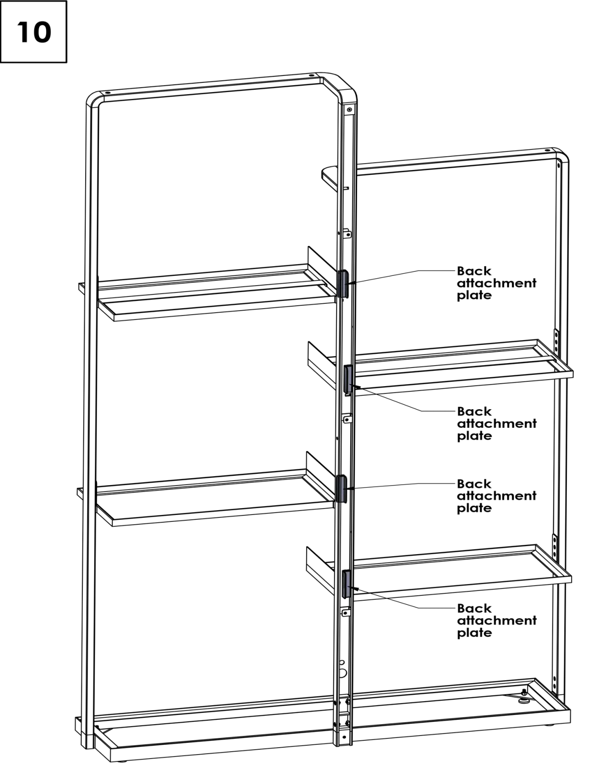
Finish the frame
Remove the part-label stickers
With a heat gun or hair dryer, heat each labeling sticker until it turns black, then peel it off.
Set the Base Box into the frame
Set the Base Box from Step 1 into the Base Frame, with the Rear Panel’s two round holes against the center Back Support Bar (B3). The lid stays off until the end of Stage 4.
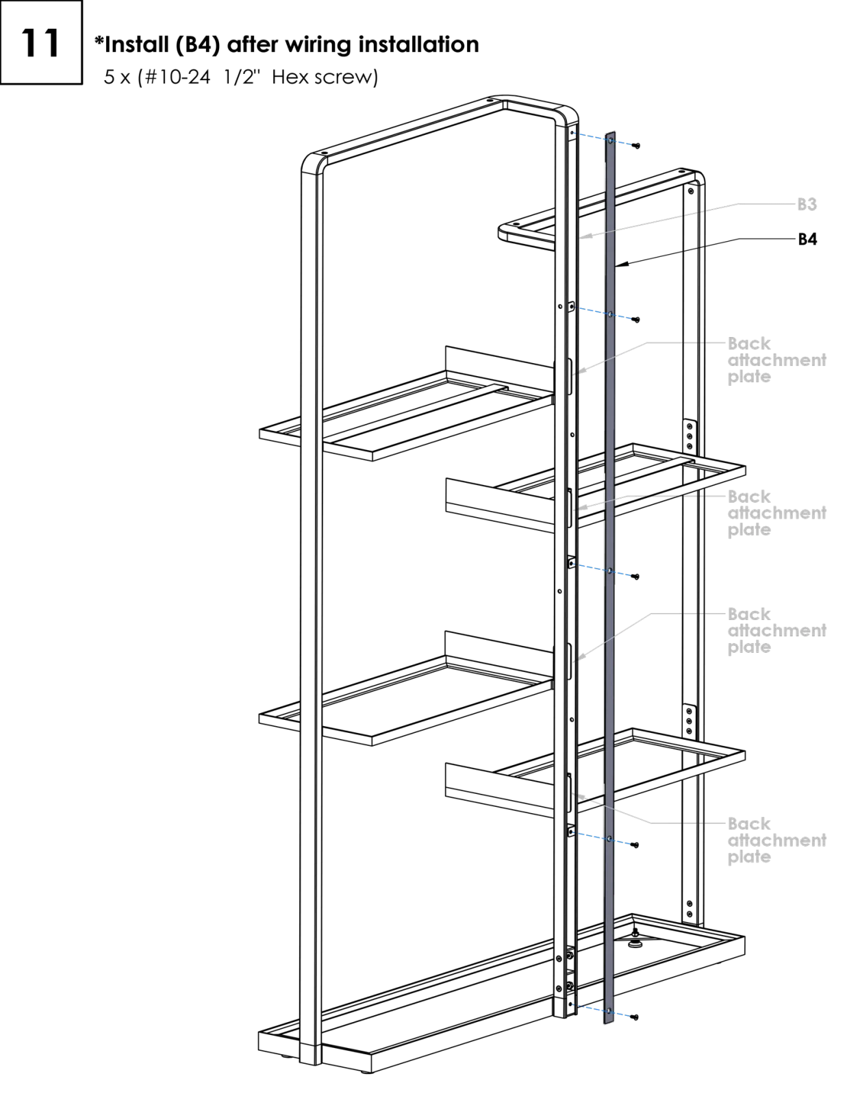
Not yet: hold the Back Plate (B4) and its five ½″ screws for the last step of Stage 4. The wiring and tubing run through the back channel first.
This step is complete when
Back Plate (B4)
The Back Plate closes the back of the center column. It is shown here for reference only: it goes on at the very end of Stage 4, once the wiring and tubing are routed. Confirm every tube and wire is clear of the channel, then fasten B4 with five #10-24 × ½″ screws. If it doesn’t sit flush near the bottom, tap it in lightly with a rubber mallet.